- Gps Proteus Library Rfid Software And Test#
- Gps Proteus Library Rfid Download The Library#
- Gps Proteus Library Rfid How To Connect A#
Gps Proteus Library Rfid Software And Test
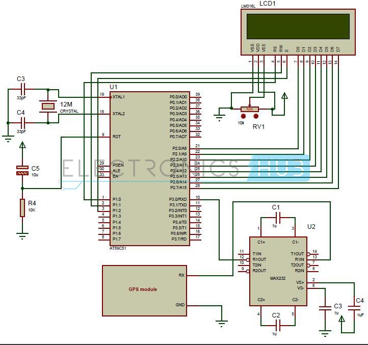
By using this simulation feature the designer can develop the systems within the software and test all the features of the system that is under design without using any hardware components. For SIM800L with RST pin, you have to use powerReset.I have skm53 in mind while designing this GPS Library for Proteus but still you can use it for any kind of GPS modules because most of them works on NMEA coding so all NMEA coded modules follow this GPS module.The Proteus simulation software can be used to interface real-time modules like the GSM Module. Yes, you read abosolutely Well, today I will share Library Proteus most anticipated and most requested. On Arduino or Genuino 101 the current maximum RX speed is 57600bps GPRS Shield 3.0. Gsm Library in proteus.After uploading the HEX file ht the simulation button and the simulation will start.
Gps Proteus Library Rfid How To Connect A
If the serial port is not available on your computer, then a USB-Serial converter can be used. The Proteus software has the option to connect with the com ports of the computer. Radio-frequency identification (RFID) is the wireless non-contact use of radio-frequency electromagnetic fields to transfer data, for the purposes of automatically identifying and tracking tags attached to objects.The GSM modules have the option to connect to the serial port of a computer through DB-9 Connector or it can be interfaced to a microcontroller using the TTL-UART feature. In this library I’m talking about RFID ( R adio- F requency ID entification). Connecting the Module to Proteus EnvironmentLibrary 23- Read RFID tag with MF RC522 on STM32F4. This article explains how to connect a GSM Module to the Proteus software and understand various commands related to the GSM module and perform some operations like sending an SMS, reading an SMS, making phone calls and so on.


Gps Proteus Library Rfid Download The Library
Properties of Comport and Virtual TerminalThe details regarding the port number to which the Serial converter is connected are obtained from the control panel under the Devices and Printers tab.We shall start interfacing the module. All these parameters should be set in the Comport and the Virtual terminal in their edit properties menu. The data is of 8-Bit mode with one stop bit and no parity. If there is any malfunctioning with respect to the data received, then next probable baud rate would be 38400. By default, the modules operate at 9600 Baud rate. Download the library below to start designing and simulating GPS projects in.Next, we have to configure the COMPORT in the Proteus software.
Every command sent to the module has to end with i.e., CR=Carriage return and LF=Line Feed characters whose ASCII values are 13 and 10 respectively.In order to check the connection, we can send the ‘Attention command’ ‘ AT’. In the C-compilers temp=‘0’ instruction will store the ASCII value of zero (=48) in the variable temp. All the command characters are viewed as ASCII characters. Below is the simulation video showing the responses after Power ON.After the response ‘call ready’ is received, the module is ready to use. The module sends some data related to the ready state of the module.

But, in real-time we have to issue this command from our microcontroller. Dialing a number from Virtual terminalThis command is issued from the virtual terminal available in the software. The command is used in the following format,Let’s try this command to originate a phone call.
Below are the function definitions. For this purpose, we have to define a function to send the ‘gsm commands’ and one more function to send data from the UART. By using arrays in the c-program, we can easily transmit the commands.
When the quotation is found, the Instruction pointer comes out of the loop as the condition is not satisfied. The contact number is declared as char contact_number This can be assigned with a default number as, char contact_number=while(received_data!=34) //Check whether the character is “ or notASCII Value of “ is 34. The size of the array can be around 20 bytes (the module allows up to 45 digits) and it should be of ‘char’ type because the data is in ASCII format. For making phone calls, we have to declare an array to store the contact number. Any data should be stored in the array format so that, the data can be handled by all the functions in the program. After sending this keyword, we have to send the destination number i.e., the contact number to whom we want to call.
The complete code to obtain number and name is shown below.Reading Number and Name of an Incoming callCLIP in the data received stands for Calling Line Identification Presentation. To fetch name from the data, the above process is repeated. So, let’s store the number into an array using the ‘for loop’.For(index=0 received_data!=34 index++,temp++)Number=received_data //Store numberNumber=13 //Terminating character for identificationNow, received_data location contains quotation mark and hence the loop is completed.
But, in real-time, the microcontroller has to read the data and identify that ‘RING’ is received. We have seen it in the Virtual terminal and performed the action. If we connect ear phones or a head set to the GSM Module, we can use it as a normal phone.By now, we have discussed how to read the received data for a particular like when ‘RING’ is received. The respective commands for these operations are,By sending the commands, the respective operation is performed. The name and number are displayed soon after an incoming call is detected.When there is an incoming call, we may have to answer the call or reject the call.
By enabling this interrupt, every byte sent by the module is stored in a variable of array type and the array index is incremented. Reading the keywords from data receivedThe UART feature has an RXC Interrupt which will generate an interrupt when a byte is received. Now, let’s discuss how to identify the keywords and execute the desired operation.
After processing the data, the array index should be set to zero. If the counter reaches a pre-set value before reading the next byte, then it is understood that the transmission is completed and the data is processed. After receiving every byte the timer is stopped, the byte is stored in the variable and the timer is initialized again. So, to identify that the transmission is completed by the module, a timer is used. The CR and LF are used to detect command line termination only and these are sent in between a command line also.
Program Snippet for Analyzing the Received DataThe first byte of the command line received will be CR (Decimal value=13) and the second byte will be LF (Decimal value=13). For ATMEGA 32, which is used in this article has the below values for 16Mhz CPU Clock, and the timer is run at Fcpu/1024.These are the output compare match registers.


 0 kommentar(er)
